|
|
|
NO5W Mobile |
|
Here
is a brief description of
the NO5W mobile setup. The diagram below shows the
configuration (configuration 2 from the What You Need
document)
currently being used.
The ConfigurationFrom an interfacing standpoint the heart of the configuration is the Navigator by US Interface. While this box is not inexpensive it is well-built and has a lot of capability that is ideal for my application requiring only one USB port to interface the radio, WinKey, and an RS-232 GPS to the Dell D400 laptop running XP. The Navigator is powered from the USB port so no separate power source and associated cabling is required. In addition it supports digital modes with its own internal sound card. Before obtaining the Navigator I used a Keyspan 1 USB x 4-RS232 port expander along with a separate WinKey to achieve a somewhat similar configuration. That approach is a less expensive option but of course doesn't have the digital mode capability and requires a separate WinKey box and associated cabling. I was also concerned about RFI getting into the plastic enclosure of the Keyspan device and/or the cabling to the WinKey, although that never happened. I thought that the Navigator, with its aluminum cabinet, would be much less susceptible to RFI. Actually RFI has not been a problem with either of the devices. One thing to keep in mind regarding use of the Navigator is that a radio-specific wiring harness is required for each type of radio. Diagrams for building your own wiring harness are on the Navigator website or you can purchase them from the vendor.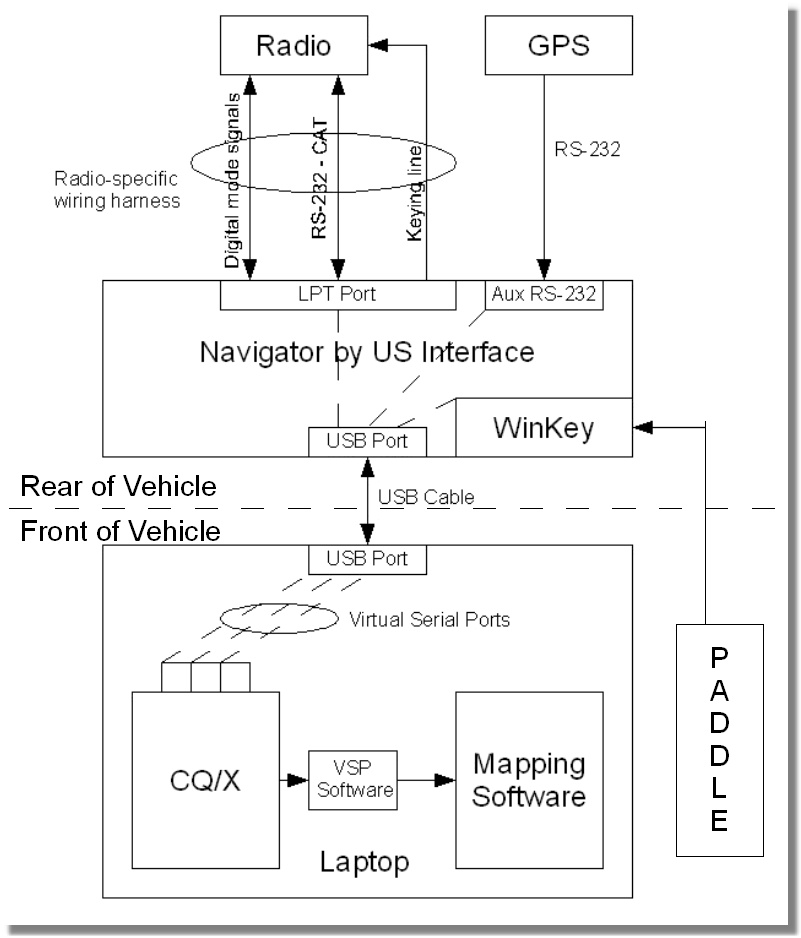 Auxiliary Battery and Interface CompartmentThe Navigator, an auxiliary 75 AHr Deka AGM battery, a West Mountain Radio Super Power Gate, and a Rig Runner are housed in a compartment of the platform that contains all of the gear in the rear of the vehicle.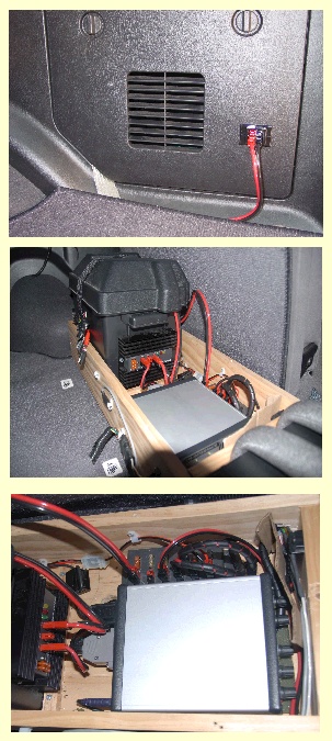 The
battery/Power Gate is setup in the W1ZR configuration with the
auxiliary battery supplying power to the radio, the laptop (via a Lind
DC/DC
converter), the GPS which is a simple Garmin PC-18DLX receiver
mounted on the driver's side window of the rear compartment, and the
MFJ 1924 antenna controller. When we
are underway with the engine on the vehicle battery shares the
load and keeps the auxiliary battery charged via the power gate.
Connection of the vehicle supply to the power gate is from a small
compartment on the passenger side of the Pathfinder and an Anderson
power pole bulk head connector. When we're stopped the auxiliary
battery has enough charge to power everything for several hours even
running the radio at maximum power output. A nice advantage of
having the auxiliary battery is that everything can be left in a
powered up state at fueling stops and other breaks. Here
are a
couple of shots of the rear platform. The silver container in
the
photos is the Navigrator interface box. When we operate multi-two from
the mobile power for everything for both stations is supplied by the
auxiliary battery except for the second radio which is supplied by the
vehicle battery. The
battery/Power Gate is setup in the W1ZR configuration with the
auxiliary battery supplying power to the radio, the laptop (via a Lind
DC/DC
converter), the GPS which is a simple Garmin PC-18DLX receiver
mounted on the driver's side window of the rear compartment, and the
MFJ 1924 antenna controller. When we
are underway with the engine on the vehicle battery shares the
load and keeps the auxiliary battery charged via the power gate.
Connection of the vehicle supply to the power gate is from a small
compartment on the passenger side of the Pathfinder and an Anderson
power pole bulk head connector. When we're stopped the auxiliary
battery has enough charge to power everything for several hours even
running the radio at maximum power output. A nice advantage of
having the auxiliary battery is that everything can be left in a
powered up state at fueling stops and other breaks. Here
are a
couple of shots of the rear platform. The silver container in
the
photos is the Navigrator interface box. When we operate multi-two from
the mobile power for everything for both stations is supplied by the
auxiliary battery except for the second radio which is supplied by the
vehicle battery. RadiosI've used a number of different radios in the mobile including IC-706 MKIIG, IC-7000, and the Elecraft K3. Currently I'm using the K3 and taking along an IC-7000 for backup. The backup IC-7000 is mounted on a small board and is attached to the top of the rear compartment just above the Navigator with all connections, except the one to the Navigator, present and ready to go. The main difficulty in changing to the backup radio is the connection to the Navigator since there is little room between the Navigator and the auxiliary battery in which to work on the connector.Of course the K3, although small and relatively lightweight, was not designed for mobile operation in the same way as the IC-7000 so there's no remote control head and no mounting bracket. Control of the K3 is via the K3 Remote that I've recently developed for CQ/X. The K3 is secured on the rear platform using materials from the local home improvement depot as shown below. The tie downs consist of rope threaded through pipe insulation and, to avoid slippage, the platform surface under the radio is lined with "waffle cloth" that is often used for lining kitchen drawers. The tie downs are tied to two small cleats on the left hand side of the radio to enable quick removal of the K3 from the vehicle. The entire rear platform is "connectored" using appropriate connectors (automotive trailer connectors, Anderson power poles, etc) for easy removal from the vehicle since this is primarily a contesting setup, not a permanent day-to-day mobile installation. When there's a long stretch between QSO parties all of the gear, with the exception of the cabling, is removed and used in my fixed station. 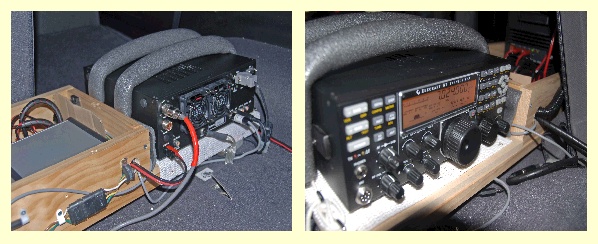
Antenna SystemI originally started out using the venerable hamsticks on tri-mag mounts for antennas and they worked quite well. However, several years ago I decided to upgrade the antenna system and purchased a HI-Q 4/80 from Hi-Q Antennas. That turned out to be a good decision as the HI-Q antennas are very well-made and provide excellent performance. Tuning of the antenna is via an MFJ-1924 controller mounted on the console near the operating position. Two proximity switches mounted 90 physical degrees apart on the antenna shaft provide control pulses to the MFJ-1924. Originally I used only a single proximity switch but have found that the antenna is much easier to control with the higher resolution provided by the additional switch. I also experimented with automatic antenna controllers but found them to be too slow and somewhat unreliable. A few hours spent with an antenna analyzer to determine the presets for the MFJ-1924 is all that's required and moving from band to band, although not instantaneous, is fairly quick. Prior to each QSO party I spend an hour or two verifying that the presets are still good and revising them if necessary. A Unun from DX Engineering provides impedance matching at the base of the HI-Q and grounding is via a two-inch copper strip from the antenna mount on the trailer hitch to the Pathfinder frame. Here are a some photos of the antenna system installation.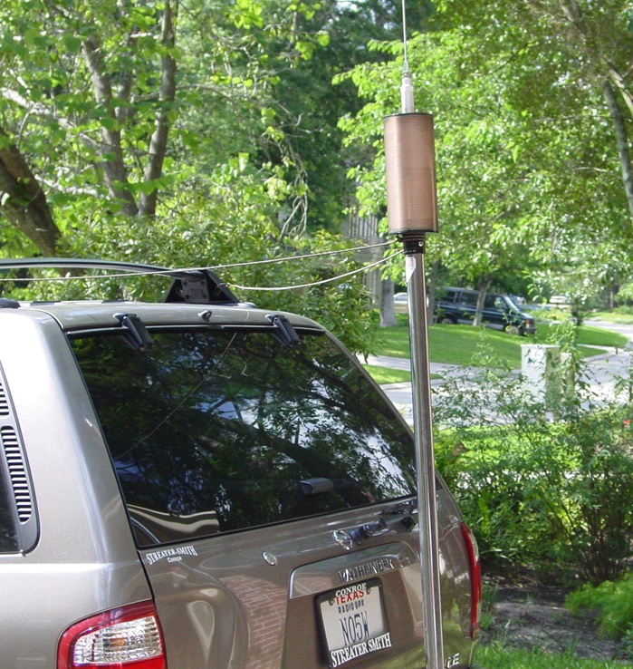 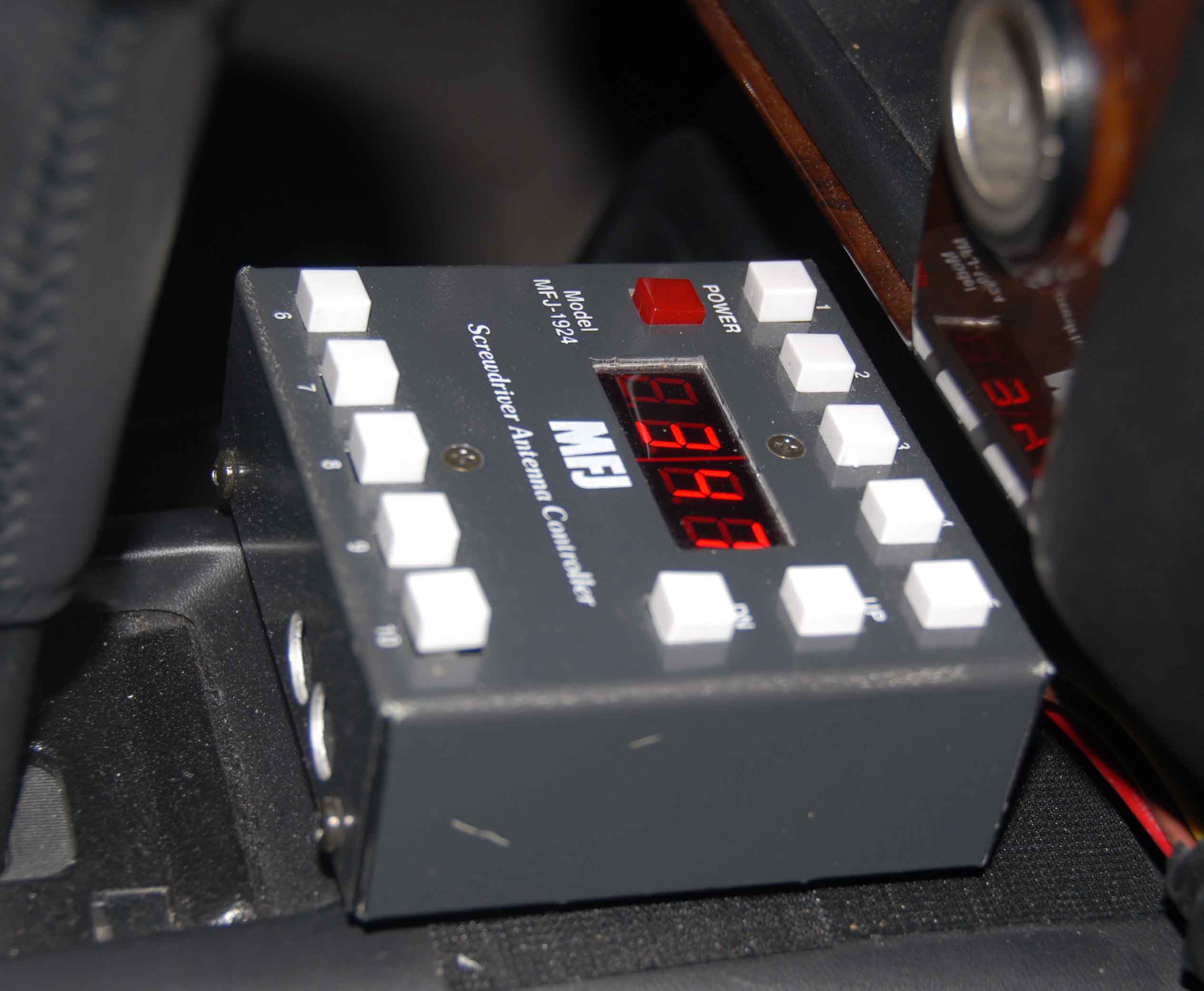 The Operating PositionThe operating position consists of the above MFJ-1924 antenna controller mounted on the console and a lapdesk containing a Dell D400 laptop, a Palm Paddle, and Heil Pro Set headphones. Connections for the Navigator USB cable, headphones to the radio, paddle to the Navigator or to the radio, and power for the laptop are all made under the operator's seat. GPS data lands on CQ/X via the Navigator USB connection and is passed to Streets and Trips via a pair of virtual serial ports. The main use of Streets and Trips is to allow the operator to help the driver in case we make a wrong turn or there is confusion about the route. Waypoints are defined in CQ/X as decision and/or turning points so that the distance to the next turn is always available to enable the operator to keep the driver informed. The Multiple Waypoint Tracking feature in CQ/X can be used to keep the distances to waypoints visible in order to at a glance inform the driver of approaching turns, etc.Glare is one of the main physical problems in using the laptop in mobile contesting depending on direction of travel, time of day, etc. We take along a small hood for the laptop in case the glare gets really bad. However, the hood tends to pop off from time to time and somewhat limits the visibility of the screen so we only use it when absolutely necessary. Here are some shots of the operating position. [Photos to follow] Powering on the radio has also been somewhat of a minor problem. Many times we will be headed down the road before I realize that the radio is not turned on. So I would have to stop, get out of the vehicle, and turn the radio on. Not a big deal but a nuisance. Recently I decided to develop a wireless remote to do this using my DroidX and the little Android IOIO board I bought from Sparkfun Electronics. It is a fun little project that I've also used to move up the Android development learning curve. It turns out that with the Android IOIO board and a few external parts you can build the hardware part of a wireless remote that can do a lot more than power on the radio. For an overview of my Wireless Android Remote for the K3 see this page. Copyright: C.W. Sanders, NO5W Last Updated: 28-January-2012 |